Integrated Lacing-Zone Reinforcement
3D Integrated Eyelet System for Cleaner Upper Assembly
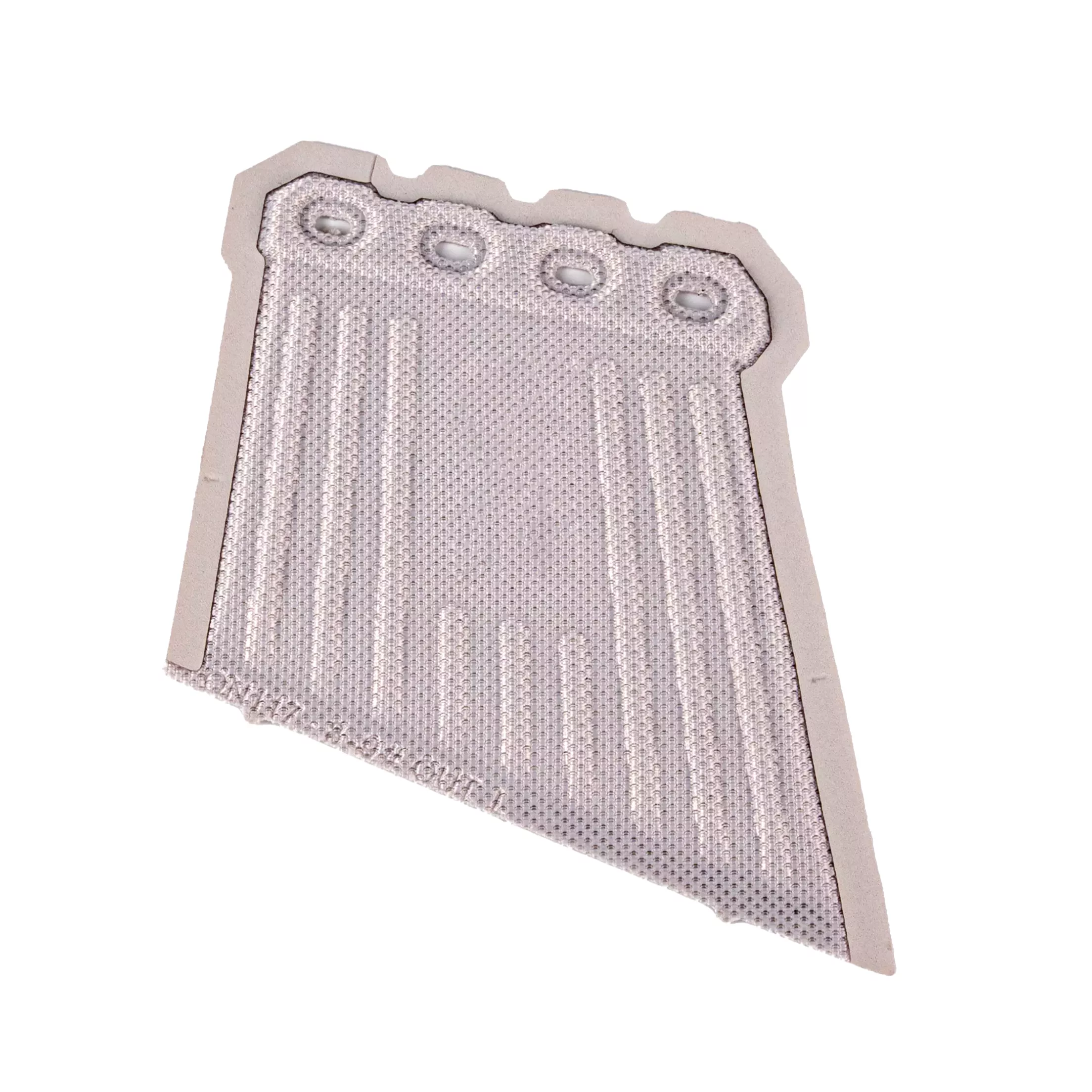
FX Footwear’s 3D integrated eyelet system combines the eyelet reinforcement area into a thermo-compression molded composite structure. The result is a more unified lacing zone with fewer added parts and fewer assembly operations. Each OEM program is developed around the upper, lace layout, surface direction and approval requirements.
Product Value
A More Unified Lacing Zone with Fewer Separate Parts
The construction treats eyelet reinforcement as part of the upper architecture. Structural intent, visible design and production sequence are considered together before the component is approved.
Integrated Structural Design
The eyelet zone is formed as one composite structure instead of being assembled from several separate reinforcement pieces.
Fewer Added Components
The approved design can remove extra metal reinforcements or separate stitching in the eyelet area, reducing part handling within the upper process.
Simplified Upper Assembly
Single-process molding consolidates structural details into one formed component and creates a more direct path from approved part to upper assembly.
Lightweight Structural Direction
The composite system is designed to maintain eyelet-zone integrity without the weight of multiple added parts. Comparative weight targets remain project-specific.
Development Framework
3D Eyelet System Selection Framework
A useful eyelet specification connects the visible lacing design with the substrate, forming route and validation plan. These decisions shape tooling, sampling and the approved upper interface.
| Development area | Project inputs | What the decision shapes |
|---|---|---|
| Eyelet layout | Hole count, diameter, spacing and lace path | Lacing geometry and local load direction |
| Molded geometry | Outline, contour, thickness profile and edge transition | Fit with the upper pattern and visible form |
| Upper interface | Base textile, surrounding layers and attachment area | Material compatibility and assembly sequence |
| Structural objective | Buyer-defined lace load, flex and abrasion criteria | Sample validation and acceptance methods |
| Surface direction | Color, texture, finish and approved visual detail | Brand expression and tooling surface |
| Size range | Grading rules, orientation and dimensional tolerances | Tooling coverage and inspection reference |
Application Fit
Footwear Programs for Integrated Eyelet Reinforcement
Application fit depends on the lacing loads, flex requirement, upper substrate and finished-shoe approval plan rather than the footwear category alone.
Running & Training
The component can be developed around lace position, upper contour and the intended hold across the midfoot.
Outdoor
Structured lacing zones can be reviewed for trail, hiking and approach footwear with project-specific load and flex criteria.
Work & Utility
Selected work or utility designs may benefit from fewer hardware parts. Safety and market requirements remain part of complete-shoe approval.
Lifestyle & Casual
Color, texture and molded form can create a dimensional eyelet area without separate visible metal hardware.
OEM & ODM Development
Custom 3D Eyelet Development
The option set is confirmed after the upper construction and forming route have been reviewed. Geometry, material interface and the assembly sequence remain connected through the sample process.
- Eyelet positions and lace path
- Hole profile and spacing
- Molded contour and thickness
- Upper substrate interface
- Edge transition and attachment
- Color, texture and finish
- Size grading and tooling
- Buyer-defined test criteria
Quality Process
From Lacing-Zone Brief to Production Reference
The process aligns the formed component with the upper construction and its agreed quality criteria. FX laboratory and testing support follows the agreed product and buyer requirements.
Development Route
Reference-sample matching or new-mold development is established alongside geometry, material and documentation needs.
Tooling & Material Review
The composite route, formed shape and upper substrate are evaluated together before the approval sample.
Golden Sample
The approved component records construction, dimensions, visual limits, tooling status and revision history.
Production Checks
First-article, process and final inspection follow the agreed specification and any buyer-defined lace-load or durability methods.
Connected Footwear Development
Why Footwear Teams Develop with FX
One-Stop Component Context
FX works across upper components, insoles and midsoles. Product teams can review how the featured component relates to the surrounding shoe instead of treating it as an isolated part.
Regional Manufacturing Coverage
Fuxiang Group runs eight factories across China, Vietnam and Indonesia. Production scope and location remain part of the individual project review.
Project-Specific Validation
In-house laboratory support follows the approved material, construction and buyer test plan. Third-party coordination is available when external reporting forms part of the program.
Buyer Questions
3D Integrated Eyelet System FAQ
What is a 3D integrated eyelet system?
It is a molded upper component that combines the eyelet reinforcement area into one thermo-compression formed composite structure. The construction is designed to reduce separate stitching or metal reinforcement parts.
Can it replace metal eyelets and extra stitching?
The approved construction can remove additional metal reinforcement and separate stitching in the eyelet zone when the substrate, geometry and validation plan allow it. The final bill of materials remains project-specific.
Does a custom eyelet component require new tooling?
A new molded shape, major geometry change or different support structure may require new tooling. The drawing, size range, material route and tolerances determine the tooling plan.
Can geometry, color and surface finish be customized?
Yes. Feasible eyelet positions, contour, color, finish and texture depend on the selected composite structure, forming process, tooling surface and approval standard.
Which footwear categories can use the system?
Potential programs include running, training, outdoor, selected work or utility, and lifestyle footwear. Final suitability depends on lacing loads, upper construction, flex and market requirements.
How is production quality controlled?
The approved sample and specification form the production reference. Project controls can cover material verification, first-article dimensions, appearance, process parameters, in-process inspection and final release.
A Connected Starting Point for Eyelet Development
Eyelet geometry, upper material, tooling route and approval criteria can be reviewed as one development package, with adjacent upper components considered within the same program when relevant.